By Philippe Dubois, Chairman.
In this eleventh article, we return to the analysis of the electronic boards of our Micral N, which has progressed enormously thanks to the joint work of Jean-François, Sylvain and Arthur. All their work has been progressively recorded on a page hosted on Jean-François' website (Hxc2001.free.fr), and in the end the overall operation of our Micral N holds almost no secrets for us - or so we hope.
But before we dive headlong into the details of each of its electronic cards, I invite you to take a look with us at the model of our machine! Indeed, when we opened the front panel of the machine, we came face to face with a plate clearly indicating which model it is and potentially helping us to give it a date of birth:
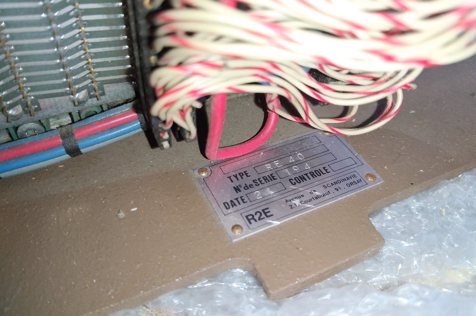
Our Micral N is a RE40 model with serial number 194!
Our Micral N would therefore be a RE40 model, with serial number 194. The one hundred and ninety-fourth machine built by R2E! Which already proves that several hundred Micral Ns were produced. As you can see, there is a 'Date' field on this plate, but with only one number, '21', and it's hard to imagine what this refers to.
Now, we have noticed other markings still on the front panel of the Micral N which may give us a more accurate estimate of its year of release:

Our Micral N could have been built on the 153rd day of 1974, but that's just a guess.
Of course, it could be the front panel which could have been modified or replaced by this date, it's hard to say. If the number 21 on the serial number plate represents the number of the week of construction in the year of our machine, that could give 7×21=147, close to the 153rd day. It's also worth noting that most of the components on our Micral N are also dated 1974.
If you know how to decipher this kind of information in French industrial buildings better than we do, don't hesitate to let us know!
Detailed analysis of maps and mapping of Micral N

Let's move on to the analysis of all the cards in the order in which they were implemented:
Card 1: 2 KB RAM card
This is one of the simplest cards. The machine's multiple static RAM cards have been placed more to the right (looking at the machine from the front) of the machine, more or less all together, with the more central part being more reserved for I/O and the cards on the left being more for control (panel, cpu, monitor, etc.). The SRAM chips are also all the same. It has to be said that back in 1973, there wasn't yet a very extensive catalogue of these!

2K 11200/S/A RAM card: 16 P2102 SRAMs (16 * 128 bytes = 2K). Address configuration: 0x2800-0x2FFF
The majority of Micral N cards are equipped with at least one bracket (shown here top right) which allows you to choose which memory address it is located at (connectors S11, S12 and S13 on this card) on the Pluribus. This address is indicated on each photo of our Micral N cards.
Card 2: 2 KB RAM card

2K 11200/S/B RAM card: 16 P2102 SRAMs (16 * 128 bytes = 2KB). Address configuration: 0x1000-0x17FF
Card 3: 2 KB RAM card
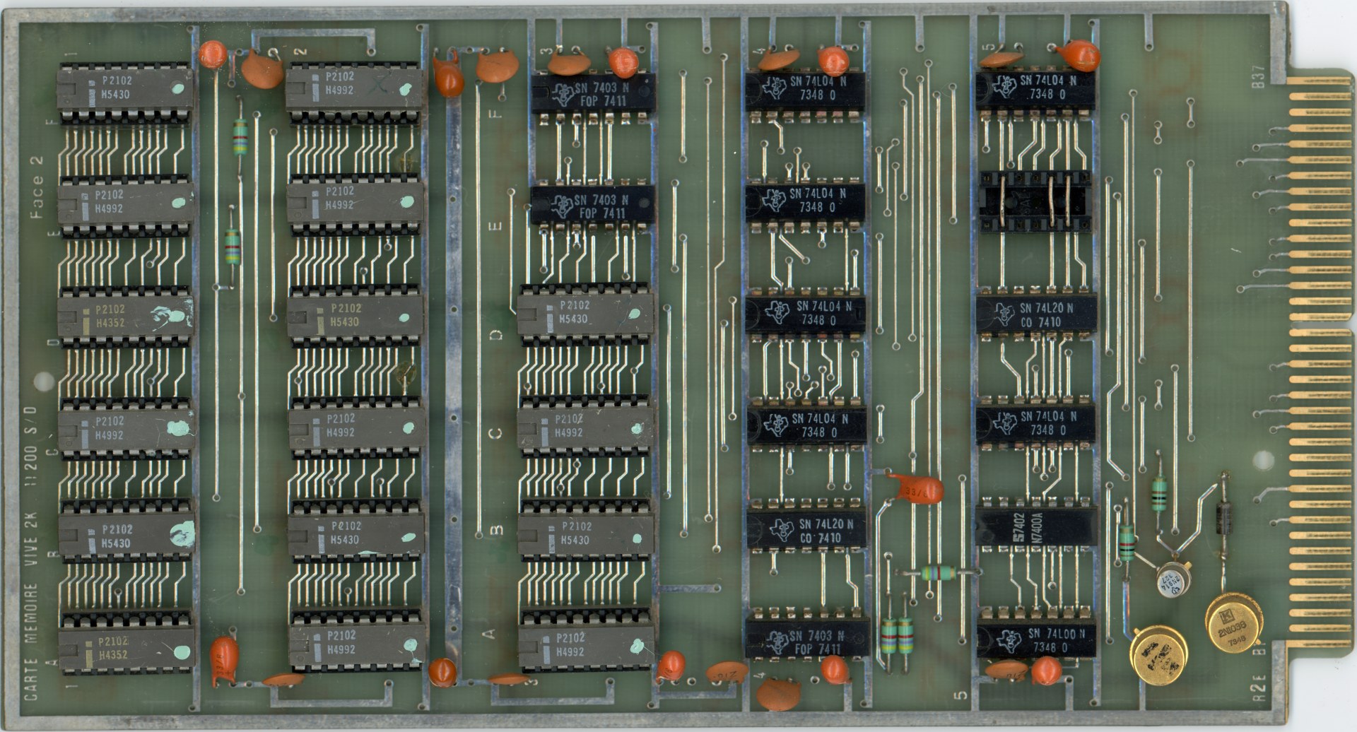
2K 11200/S/D RAM card: 16 P2102 SRAMs (16 * 128 bytes = 2KB). Address configuration: 0x1800-0x1FFF
Card 4: 2 KB RAM card

2K 11200/S/A RAM card: 16 P2102 SRAMs (16 * 128 bytes = 2KB). Address configuration: 0x2000-0x27FF
Card 5 : 2 KB RAM card

2K 11200/S/A RAM card: 16 P2102 SRAMs (16 * 128 bytes = 2KB). Address configuration: 0x3000-0x37FF
All these 2KB memory cards are relatively identical, optional and can be placed in any order in the Micral N.
When we studied these cards and the Pluribus backplane of our Micral N, we also realised that the memory of our machine can be maintained in the event of a power cut, certainly by an external box equipped with batteries or even a form of inverter. One of the Micral N's power sockets is stamped '+5V Backup'.
Card 6: 4KB RAM card and boot ROM

12400/SB card: 32 SRAMs P2102 (32 * 128 bytes = 4KB) + 1 EPROM 1702A (256 bytes containing the bootstrap). SRAM Address configuration: 0x0000-0x0FFF, EPROM Address configuration: 0x0000-0x00FF
This card is, as you can imagine, particularly important and, we assume, must have been present in one way or another in all Micral N models, since it both acts as the machine's boot ROM, and also provides 4 KB of RAM that allows it to work immediately.
Slot 7 is free, so we go straight to 8.
Board 8 : Board 32-32 (Input/Output board)

32-32 10900/S (indA) card: I/O card. IO Base address: 0xC (Logic: 0x4/0x1)
This card appears to be relatively symmetrical, and can ensure dialogue between the Micral N and an external peripheral, hence the connectors on each side of the card.
Board 9: Board 32-32 (Input/Output board)

32-32 10900/SC card: I/O card. Special card marked "Lecteur MDS
The purpose of this card is not yet known. The name MDS may refer to an external system marketed by Intel (MDS).
Site 10 is also free, so we'll move on to the next stage.
Card 11: Asynchronous coupler

Asynchronous coupler 11100/SC: AY-5-1012 serial interface.
This card is a serial communication interface using an early version of the General Instruments AY-5-1012 chip. It is connected to and controlled by a 32-32 board (in position 19 in this Micral N). It has no real link with the Pluribus apart from the system reset and the power supply, hence the few connected pins visible on the comb on the right. The default setting is 110 baud, 8 bits, no parity bit (i.e. approximately 10 characters per second!). An important detail for what follows is that it uses a 7-bit mode with parity emulated by software via the internal monitor. We should be able to connect to it to talk to the machine!
Three more free slots take us directly to slot number 15.
Card 15 : Coupler trainer card

13400 SA coupler formatter board (N): Floppy drive controller. Base address: 0x14
This card is in fact a floppy drive controller, but 100% in wired logic. At this stage, and as Sylvain mentioned this in article 10We believe that this card was used to connect an external 8-inch floppy disk drive using 'hard sector' floppy disks (the sectors are fixed when the floppy disk is created), one of the very first 8-inch floppy disk formats.
According to our deductions, the disk format managed by the bootloader is 256 KB, 1 side, 64 tracks, 32 sectors of 128 bytes per track, FM hardsector format.
Map 17: Pile_channel map

10300/SA stack_channel card: Address base: 0x1E (Logic: 0x16/0x6)
This card is used as a battery by the bootloader and the internal monitor. We can repeat the explanations given by Sylvain in article 10 concerning the specific operation of these cards:
"These 'stack_channel' cards are important for the operation of the Micral N, even if they are not technically essential. They are memory cards which interface on one side with the PLURIBUS, and therefore with the rest of the machine. On the other, they can be connected to another card for direct communication, independent of the processor. In 'stack' mode, the card behaves like a computer stack: whatever is written last in the memory is read first (LIFO); in 'channel' mode, data is read starting with the oldest to have been written (FIFO)."
Map 18: Pile_channel map

10300/SB stack_channel card: Address base: 0x1D (Logic: 0x15/0x5)
As seen previously when analysing board 15: coupler formatter board, this board is used in channel mode for the floppy controller, and is used to manage an input/output buffer with the drive.
Map 19: Map 32/32

32-32 10900/S card (indB) : Address base: 0x8 (Logic: 0x0/0x0)
As mentioned in the analysis of board 10: asynchronous coupler, this board is used with the Micral N serial port.
Card 20: 8008 processor card

Processor card 10200/S ind B: Intel 8008, Frequency ~500 KHz
This is one of the first electronic boards we saw together in the first article on theanalysis of the electronic boards in our example of Micral N ! The heart of it all, and the one we saw 'beating' for the first time in the previous article: https://mo5.com/premier-demarrage-du-micral-n/
Card 21: Monitor memory card

10400 SB memory card: Monitor. 8 EPROMs 1702A (256 bytesx8, 2 KB total containing the monitor). Address configuration: 0x3800-0x3FFF
This card therefore contains the monitor that we had already dumped, 2 KB in size, and which allows access to supervision and control commands when the computer calls on it. The operation of the Micral N front control panel was filmed and will be shown in a future article.
Map 22: Console map

11600/S_B console board: Front panel LED and switch management board
This is the board that manages the LEDs and control switches on the Micral N front panel. It manages changes in the status of the machine and the various related LEDs on the panel.
After a visual overview of all the maps of our Micral N, and for the more technical amongst you, we invite you to visit the page dedicated to the restoration project of our Micral N on Jean-François' website at this address : http://hxc2001.free.fr/micral-n/
Conclusion of the study
Finally, with the knowledge gained from analysing all these cards, we can finally draw up an ideal operating diagram for our Micral N model RE40 :

Operating diagram for Micral N RE40 from the MO5 association
Meanwhile, the programming of our Micral N is making great strides and we'll soon be able to run a programme of our own. And we can't wait! But that's for a later article, of course. In the meantime, don't forget to take part in our campaign! https://micral.mo5.com