Welcome to this new article, which we hope will be the first in a series dedicated to first aid for our dear old machines to keep them in good working order!
To be more precise, you won't find in these articles how to repair a broken power supply, change specific components unless they are easily replaceable, or methods on how to properly solder electronic components, for example. However, you can find information on the internet, and in particular on Youtube a number of video tutorials to give you some ideas. If you have the slightest doubt, there's only one thing to do: come and discuss it on our Discord !
Our first article will therefore be dedicated to the Atari STf or STe, a range of machines that are dear to our hearts and with which many of our members had their first computer thrills. More than thirty years after the machine's release, it is in need of some first aid, which we are going to carry out together.
Table of contents (click to go directly to the heading) :
- Materials required
- Dismantling the Atari ST
- Recapping the feed
- Repairing or cleaning the Atari ST keyboard
- Re-insert the internal chips in their holders
- Cleaning the mouse
- Cleaning the diskette drive
- Deoxidation of connectors
- Put your Atari ST back together!
Materials required
You will need the following materials for this workshop:
- A set of Philips Phillips screwdrivers and a small flathead screwdriver
- Small flat-nose pliers
- A minimum 25 watt soldering iron with a little solder for electronics, a pump or desoldering braid
- New capacitors, a list of which can be found in the section on power supplies below.
- A few cotton buds and a pure alcohol-based solution, with no additives
- A small brush to dust the various components of the machine at each operation
- A can of electrical contact cleaner
- Lithium grease for mechanical parts
What's more, we will be working throughout this article on an Atari 1040 STf which belongs to Jean-François Freitaswho is none other than the musician who worked on the Atari ST version of Another World!

Jean-François Freitas' Atari 1040STf before dismantling
Cleanly dismantling your Atari ST :
First of all, take a Phillips screwdriver and a small pair of flat-nose pliers. Turn your ST over on the front (place it on a cloth, for example, to avoid scratching it) and unscrew all the screws circled in blue and green. However, don't mix them up: the screws circled in green are those for the plastic body, the screws circled in blue are those that hold the internal floppy drive in place. If it helps, use different containers for each category of screw (body, internal metal shield, floppy drive).

Screws to be removed from under the bodywork.
Once the screws have been removed, you can turn your Atari ST over and place it face up again, and carefully remove the entire upper body by lifting it vertically. It should come off without too much difficulty. At this stage, you can already clean the upper body with lukewarm water and a little pure soap to remove dust and traces of use.
Warning: Atari ST body plastics do not age well and tend to become brittle. So be careful not to force the body when you remove it!
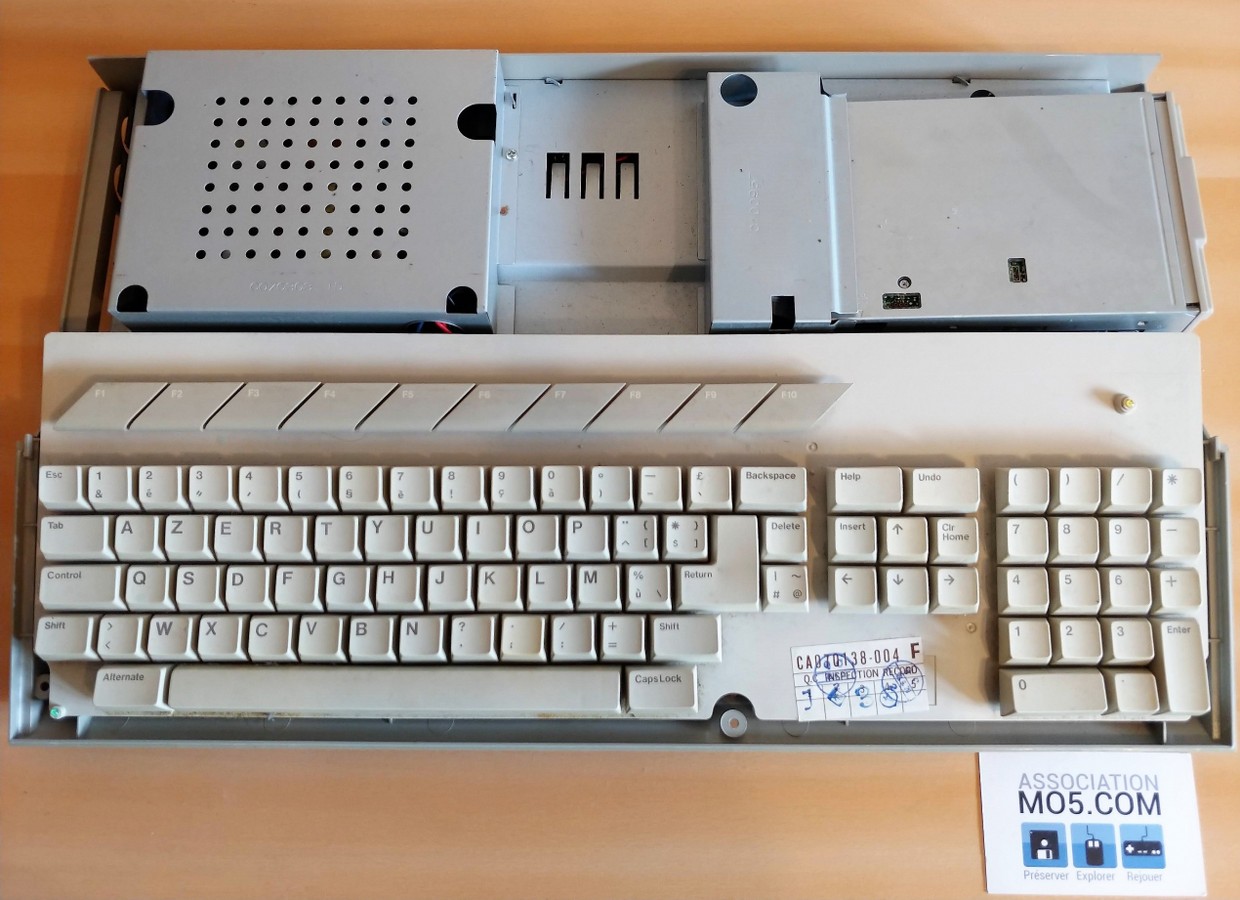
Remove the top cover to access the keyboard
Now you can lift the keyboard, which is not attached to the case, taking care not to pull on the cable that attaches it to the motherboard.
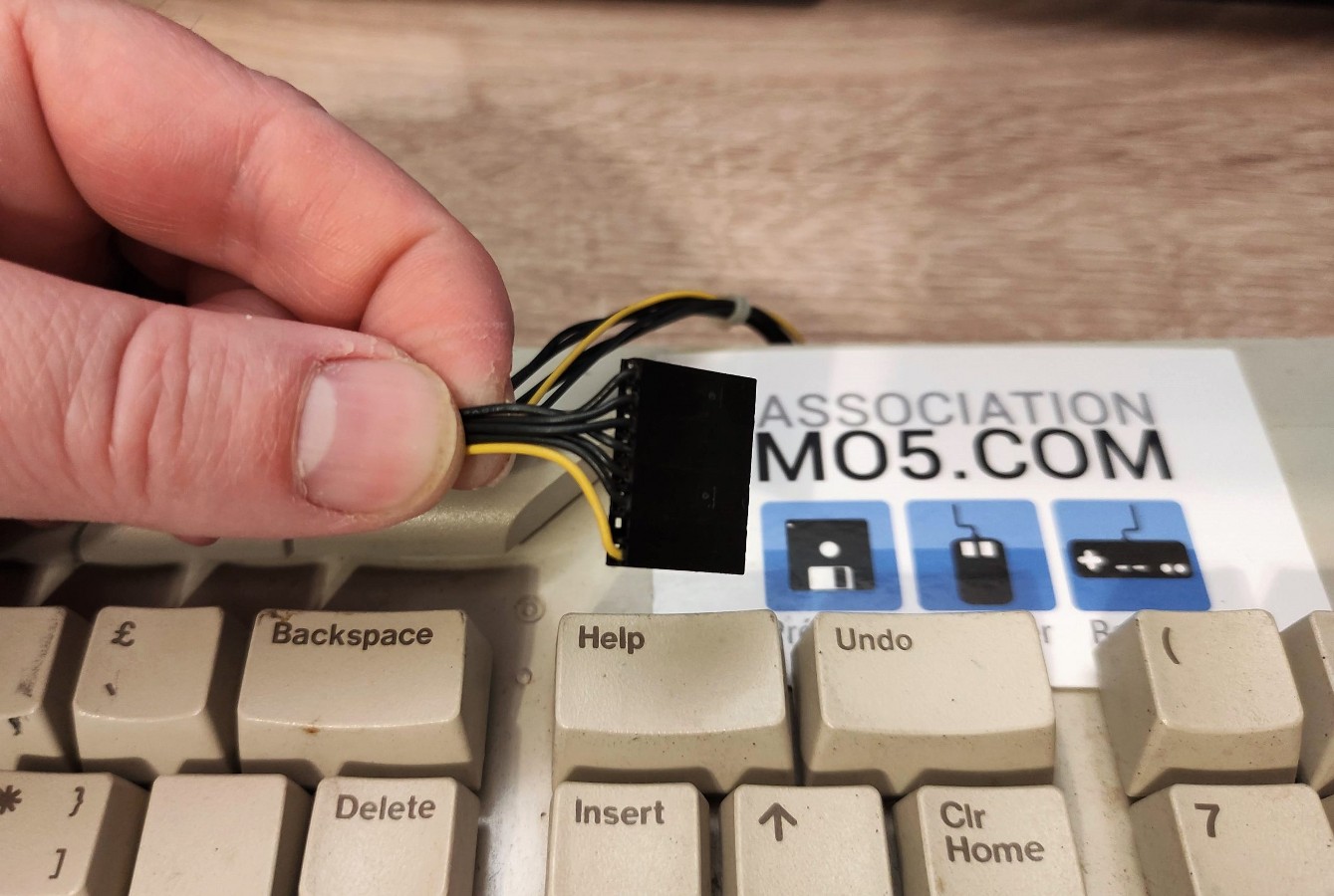
The yellow cable indicates the direction
To detach this cable, grasp the connector with your fingers and pull upwards. There should be no resistance. Note that the keyboard connector has a polariser, so it will be relatively easy to put it back in place.

With the keyboard out of the way, it's time to tackle the armouring!
The metal covers on the Atari ST motherboard must be removed one by one in two stages:
- By unscrewing the metal screws
- Unfold the metal lugs used to clamp the two parts of the armour.
To remove them, take the flat-nose pliers and, holding them vertically, pinch the pin and rotate it so that it is straight and the metal part can be easily removed:

Illustration of the procedure for removing the shield using flat-nose pliers
This is what a straightened metal pin looks like:

With the clamp straightened, you can now remove the armour.
So there you have it, access to all the ins and outs of your ST. And now we're going to take a look at a vital aspect of its health: its food!
Recapping the power supply :
The term recap (replacing old capacitors with new ones, which potentially avoids serious electrical problems.
A capacitor is in fact mainly used as a kind of energy reserve that provides the machine's components with a stable operating voltage. Older capacitors tend to malfunction and lose their reserve capacity, which can affect the quality of the voltages received by the components, even damaging them.
Warning: as a general rule, be sure to unplug your machine at least a few minutes before dismantling.
Remove the power supply unit from your Atari ST by unscrewing the two screws (circled in blue) that hold it to the motherboard (the one on the right is behind the wires in the photo):

Remove these two screws to remove the power supply.
You can then unclip the PSU from the motherboard. The capacitors to be replaced are circled in red and green in the following photo:

Atari 1040 STf power supply circuit capacitors and screws
- The capacitor circled in red is the main power capacitor. It is a 400 V and 68 µF model (400 volts and 68 microfarads, the unit for measuring capacitor capacity).
- The capacitors circled in green are those that supply power directly to the Atari ST, and are often low-voltage capacitors: between 10 and 16 volts, for example.
Here are the two most common models:
- Taiwan Liteon PE-2350-2 (the model featured here) :

- 1x 400 V, 47 µF
- 2x 16 V, 3300 µF
- 2x 25 V, 2200 µF
- 1x 10 V, 10 µF
- 1x 50 V, 1 µF
- Mitsumi S02 :

- 1x 400 V, 47 µF
- 2x 10 V, 2200 µF
- 1x 16 V, 2200 µF
- 1x 50 V, 1 µF
- 1x 16 V, 1000 µF
- 1x 10 V, 1000 µF
Caution: Pay attention to the dimensions of the capacitors you are replacing. It is important to use good quality capacitors (Panasonic, Multicomp pro, Nichicon).
Unscrew the four screws circled in blue in the previous photo which hold the power supply printed circuit board to its metal support and turn the board over as follows:

Location of capacitor leads to be replaced.
But above all, pay attention to the polarity! The white stripe on each capacitor indicates the negative pole, and you must scrupulously respect the original direction! If you're not sure, take photos to compare before and after fitting each new capacitor.
That's it, your ST power supply is now ready to be used for many years to come! We'll move on to the next stage, and you can reassemble it whenever you like.
Repair or clean the Atari ST keyboard :
All the computers in the ST range, apart from the Mega ST series, share the same type of dome keyboard. But as well as cleaning the keys, which can only be done in depth by completely dismantling the keyboard, we're also going to look at how to repair one of the most common ST problems: soldering of the joystick sockets. This is most often characterised by either the mouse no longer working or not working properly (the cursor won't go up, for example), or the joysticks not responding properly (loss of direction, or firing buttons, etc.). It's easy to fix these problems, but unfortunately you have to dismantle the keyboard to do so.
Caution: Be very careful not to lose the rubber domes on the keys or the small screws on the keyboard!
Hold the keyboard in front of you and remove all the visible screws, including those under the adhesive. For the latter, you can cut a notch around the screw. However, make sure you don't remove it, as it prevents short circuits.

Back of keyboard module
Now you can remove the PCB from the keyboard, but make sure you do it vertically! Some of the keyboard's domes could get stuck to the printed circuit and you risk losing them. Once open, the keyboard looks like this:

Location of joystick sockets and positioning of key domes.
Note that a dome has stuck to one of the keys at the top! You'll need to be particularly careful when you reassemble the keyboard to ensure that this dome returns to its place. Now we've circled the two DB9 joystick/mouse sockets on the keyboard in red. Cleanly re-solder the nine points. Once this is done, you can carefully reassemble your keyboard, checking after assembly that all the keys work properly.
Re-insert the internal chips in their holders:
Over time, and especially with movement, the simple act of handling your ST moves certain internal chips by a few tenths of a millimetre. Some chips will come out of their holder and no longer work properly! Or the oxidation of their contacts can cause communication problems between the chips and the motherboard.
Fortunately, this is quite rare, and the procedure for rectifying it is very simple. Remove the metal protection from the motherboard:

Location of the various chips to be checked and the video processor shield.
The important areas of the motherboard for our operation are circled above: the red area contains the ROMs of your Atari ST, i.e. the chips that contain the TOS, its operating system, and its graphics interface, GEM. The blue zone is reserved for the video chip. Finally, the green zone contains the chips in charge of managing your ST's memory and I/O.
Now we're going to check that the Atari ST's video chip is correctly positioned in its holder. Lift the metal cover shown in blue in the previous photo:

The video processor is accessible once the metal cover has been removed
Now take your small flathead screwdriver, and pry like this:

Use a flathead screwdriver to pry and reposition the chips on their holders
Lift the chip by about a millimetre (its support should crack a little, crrk!) and with your finger, put it back in its place. Do the same if possible at the other end of the chip, and that's it, we're done with it. We advise you to do the same with your ST's ROM chips!
Cleaning your floppy drive :
The internal floppy disk drive in your Atari ST is often a good quality Epson model. These are reliable drives, but a minimum of maintenance will enable them to perform their essential functions for longer: reading and ejecting floppy disks.
Remove the floppy drive from your Atari ST by carefully disconnecting the grey control ribbon and the power plug. At the same time, make sure you don't lose the brass part that supports the drive, circled in blue in this photo.

Watch out for the cylindrical brass part that supports the floppy drive.
Now open the metal cover of your floppy drive. There are two ways of doing this, depending on the model of drive:
- a model with a classic metal cover like the photo below, easy to remove by removing a small retaining screw on the side;
- a model using a fairly thin metal sheath into which the entire drive slides.
Take the opportunity to dust the player gently with your brush.
This gives us access to the read head:

You can access the read heads once the floppy drive is open.
Clean the upper and lower read heads with a pure cotton swab dipped in the purest alcohol solution possible. Avoid coloured or perfumed alcohol solutions, and avoid all additives. Gently rub the two heads from left to right, lifting the upper head very slightly as follows:

Insert a cotton bud soaked in alcohol and gently rub the read heads.
Now we're going to grease the drive so that the head and ejection mechanisms work properly.
To do this, take your lithium mechanical grease and apply a little to the areas indicated by the blue circles in the following photo.

Apply your lithium grease where indicated
Cleaning the mouse :
Now that your Atari ST is up and running, it would be a shame not to be able to control it because of a dirty mouse. So the next task in this workshop will be to completely dismantle your Atari's mouse so that it can be thoroughly cleaned.
To do this, unscrew the two screws on the underside of the mouse, and remove the upper casing. Then carefully disconnect the mouse cable from the internal board.
Wash the mouse ball and the two body parts in warm soapy water. To clean the cable, use a slightly damp cloth. Next, take your small flathead screwdriver, and using the tip of the screwdriver, gently scrape off any rubber or dirt that has accumulated on the rollers.

The different components of the mouse
Rewind, revisit, perfect!
Deoxidation of connectors :
Oxidation of connectors can cause false contacts. We will therefore use a specialised product to clean electrical contacts.
So take your can of contact cleaner and spray it on the following connectors:
- the video socket ;
- external diskette drive socket ;
- the cartridge port on the side;
- the two joystick sockets on the keyboard ;
- ASCI socket for external hard disk ;
- etc.
Put your Atari ST back together!
Here we are at the very last stage of this workshop! Before continuing, we advise you to place a label in your revised ST with today's date: After all, if you or someone else opens it in 10, 20 or 30 years' time, you'll be glad to remember the date you did it!
It is important to remember that ageing plastics are fragile and certain precautions must be taken when reassembling them:
- When screwing back in, first turn the screw in the opposite direction until you feel a "tick", indicating that the screw has entered its original pitch;
- do not screw in more than necessary, as applying too much force could damage the plastics.
You can now test your beautiful, well-cared-for Atari ST. If you've followed this tutorial carefully and your machine doesn't have any serious problems, it should turn on and work as it did in its early days 😉

Jean-François' Atari 1040 STf is ready to play Lode Runner!
We'd like to thank Jean-François Freitas for his confidence in us and for entrusting us with his Atari 1040 STf. He tells us he's delighted with the way it works: "The Atari works, and the first few floppy disks play fine. It's a bit strange to come back to it, it's so out of date. A big thank you in any case. It's going to keep me busy over the next few weeks!
We hope you have enjoyed this article, and we invite you to visit our server once again. DiscordIf you'd like to support us, sign up for the association's Tipeee! https://fr.tipeee.com/association-mo5-com
Main editor : Philippe Dubois "Prez
Many thanks to all the members of the MO5 association who contributed to this article: Altomare, Yoann, Mapti89, Moonbeam, Mokona78, Will, SbM